WEATHER REPORTS AND FORECASTS
Any glider flight beyond the immediate airport area requires a significant amount of scheduling and planning, usually involving others in addition to the pilot. Thus the ability to forecast whether the weather will make it all worthwhile is a desirable skill. A good knowledge of the meteorological subjects previously discussed will help the pilot make a personal forecast. One should also know how to obtain assistance in the form of aviation weather services, if not to improve the forecast at least to improve the chances of passing the knowledge and practical tests.
In 1996 the U.S. adopted the international weather reporting code for hourly surface observations (Aviation Routine Weather Report - METAR) and terminal forecasts (Aviation Terminal Forecast - TAF).
Both use the same codes where applicable. TAFs are scheduled four times daily for 24-hour periods beginning at 0000Z, 0600Z, 1200Z, and 1800Z.
Examples of METAR and TAF reports are given below and their interpretation is described in the table that follows.
AVIATION TERMINAL FORECAST (TAF)
TAF KPIT 091730Z 091818 15005KT 5SM HZ FEW020 WS010/31022KT
FM 1930 30015G25KT 3SM SHRA OVC015 TEMPO 2022 1/2SM +TSRA OVC008CB
FM0100 27008KT 5SM SHRA BKN020 OVC040 PROB40 0407 1SM -RA BR
FM1015 18005KT 6SM -SHRA OVC020 BECMG 1315 P6SM NSW SKC
AVIATION ROUTINE WEATHER REPORT (METAR)
METAR KPIT 091955Z COR 22015G25KT 3/4SM R28L/2600FT TSRA OVC010CB 18/16 A2992 RMK SLP045 T01820159
| FORECAST | EXPLANATION | REPORT
|
|---|
| TAF
| Message type: TAF-routine or TAF AMD-amended forecast, METAR-hourly, SPECI-special or TESTM-non-commissioned ASOS report
| METAR
|
| KPIT
| ICAO location indicator
| KPIT
|
| 091730Z
| Issuance time: ALL times in UTC "Z", 2-digit date, 4-digit time
| 091955Z
|
| 091818
| Valid period: 2-digit date, 2-digit beginning, 2-digit ending times
| |
| In U.S. METAR: CORrected observation; or AUTOmated observation for automated report with no human intervention; omitted when observer logs on
| COR
|
| 15005KT
| Wind: 3 digit true-north direction, nearest 10 degrees (or VaRiaBle); next 2-3 digits for speed and unit, KT (KMH or MPS); as needed, Gust and maximum speed; 00000KT for calm; for METAR, if direction varies 60 degrees or more, Variability appended, e.g. 180V260
Whenever a wind shift occurs, "WSHFT" will be included in remarks followed by the time the wind shift began, e.g., WSHFT 30 FROPA "Wind shift at three zero due to frontal passage."
| 22015G25KT
|
| 5SM
| Prevailing visibility; in U.S., Statute Miles & fractions; above 6 miles in TAF P6SM.
| 3/4SM
|
| Runway Visual Range: R; 2-digit runway designator Left, Center, or Right as needed; "/", 4-digit value, Feet in U.S.
| R28L/2600FT
|
| HZ
| Significant present, forecast and recent weather. (See following table)
| TSRA
|
| FEW020
| Cloud amount, height and type: SKy Clear 0/8, FEW >0/8-2/8, SCaTtered 3/8-4/8, BroKeN 5/8-7/8, OVerCast 8/8; 3-digit height in hundreds of ft; Towering Cumulus or CumulonimBus in METAR; in TAF, only CB. More than 1 layer may be reported or forecast. In automated METAR reports only, CLeaR for "clear below 12,000 feet". Vertical Visibility for obscured sky and height "VV004".
There is no provision in the METAR code to report partial obscuration or ceiling.
For aviation purposes, the ceiling is the lowest broken or overcast layer, or vertical visibility into an obscuration.
| OVC 010CB
|
| Temperature: degrees Celsius; first 2 digits, temperature "/" last 2 digits, dew point temperature; "M" (Minus) for below zero, e.g., M06
| 18/16
|
| Altimeter setting: indicator and 4 digits; in U.S., A-inches and hundredths
| A2992
|
| WS010/31022KT
| In U.S. TAF, non-convective low-level (<= 2,000 ft) Wind Shear; 3-digit height (hundreds of ft); "/"; 3-digit wind direction and 2-3 digit wind speed above the indicated height, and unit, KT
| |
| In METAR, ReMarK indicator & remarks. For example: Sea- Level Pressure in hectoPascals & tenths, as shown: 1004.5 hPa; Temp/dew-point in tenths °C, as shown: temp. 18.2°C, dew-point 15.9°C; ThunderStorm and RAin began at two four.
| RMK SLP045 T01820159 TSRAB24
|
| FM1930
| FroM and 2-digit hour and 2-digit minute beginning time: indicates significant change. Each FM starts on a new line, indented 5 spaces
| |
| TEMPO 2022
| TEMPOrary: changes expected for <1 hour and in total, < half of 2-digit hour beginning and 2-digit hour ending time period
| |
| PROB40 0407
| PROBability and 2-digit percent (30 or 40): probable condition during 2-digit hour beginning and 2-digit hour ending time period
| |
| BECMG 1315
| BECoMinG: change expected during 2-digit hour beginning and 2-digit hour ending time period
| |
The following abbreviations and/or symbols appear in METAR reports and TAF forecasts:
Intensity - applies only to the first type of precipitation reported. A "-" denotes light, no symbol denotes moderate, and a "+" denotes heavy."
| DESCRIPTOR | PRECIPITATION | OBSCURATION | OTHER
|
MI Shallow
BC Patches
PR Partial
TS Thunderstorm
BL Blowing
SH Showers
DR Drifting
FZ Freezing
|
DZ Drizzle
RA Rain
SN Snow
SG Snow grains
IC Ice Crystals
PL Ice Pellets
GR Hail
GS Small hail/snow pellets
UP Unknown precipitation in automated observations
|
BR Mist 5/8-6sm
FG Fog <5/8sm
FU Smoke
VA Volcanic ash
SA Sand
HZ Haze
PY Spray
DU Widespread dust
|
SQ Squall
SS Sandstorm
DS Duststorm
PO Well developed dust/sand whirls
FC Funnel cloud
+FC tornado/waterspout
VC Vicinity, 5 to 10SM
|
PIREP
The most up-to-date weather information, and often the most accurate, is that which comes from a pilot actually in the weather. Pilots are urged to file PIREPs, especially when the actual weather is different from that forecast, and to request them when talking to briefers. The following table identifies the elements that may be included in a PIREP, each preceded by a slash, and a description of each element.
PIREPS come in two varieties: "UA" Routine PIREP, and "UUA" Urgent PIREP.
| /OV | Location: Use three- or four-letter NAVAID identifier and six-digit radial and distance
|
|---|
| /TM | Time: UTC in four digits
|
|---|
| /FL | Altitude/Flight Level: three-digit in hundreds of feet
|
|---|
| /TP | Type Aircraft: Four digits maximum, if not known use "UNKN"
|
|---|
| /SK | Sky cover: Cloud cover (FEW, SCT, BKN, OVC); Cloud base in hundreds of feet MSL; Cloud "TOP" in hundreds of feet MSL
|
|---|
| /WX | Weather: Flight visibility first (e.g. FV03). Use standard METAR coding, intensity "-" light, "+" heavy
|
|---|
| /TA | Air Temperature in Celsius: If below zero, prefix with "M"
|
|---|
| /WV | Wind: Direction and speed in six digits
|
|---|
| /TB | Turbulence: Use standard contractions for intensity and type (use CAT or CHOP when appropriate). Include altitude only if different than /FL
|
|---|
| /IC | Icing: Describe using standard intensity and type contractions. Include altitude only if different than /FL
|
|---|
| /RM | Remarks: Use free form to clarify the report and type hazardous elements first
|
|---|
An example of a PIREP follows:
UA /OV OKC 063064/TM 1522/FL080/TP C172/TA M04/WV 245040/TB LGT/RM IN CLR This PIREP decodes as follows: Pilot Report, 64 nautical miles on the 63 degree radial from Oklahoma City VOR at 1522 UTC, flight level 8,000 feet. Type of aircraft is a Cessna 172. Outside air temperature is minus 4 degrees Celsius, wind is 245 degrees at 40 knots, light turbulence and the aircraft is in clear skies.
AVIATION AREA FORECAST (FA)
"An aviation Area Forecast (FA) is a forecast of general weather conditions over an area the size of several states. It is used to determine forecast en route weather and to interpolate conditions at airports which do not have TAFs issued."
(3) FAs are issued 3 times a day for the 6 areas in the contiguous 48 states. They contain four categories of information:
(1) COMMUNICATIONS AND PRODUCT HEADERS
This section identifies the office issuing the FA and the date and time of issue (DDHHMM). It also gives the valid times (DDHHMM) for the SYNOPSIS and the CLDS/WX and the states that make up the forecast area.
(2) PRECAUTIONARY STATEMENTS
This section includes a warning about AIRMETs and reminds pilots about the hazards of thunderstorms and that altitudes in the forecast are MSL unless specifically denoted as AGL or CIG (ceiling).
(3) SYNOPSIS
"The SYNOPSIS is a brief summary of the location and movements of fronts, pressure systems, and the circulation patterns for an 18-hour period."
(3)
(4) One or more VFR CLOUDS AND WEATHER (VFR CLDS/WX) sections
"Hazardous weather, i.e., IFR, icing, and turbulence conditions, are not included in the Area Forecast, but are included in the In-Flight Aviation Weather Advisories.
This section contains a 12-hour specific forecast, followed by a 6-hour categorical outlook giving a total forecast period of 18 hours.
The specific forecast section gives a general description of clouds and weather which cover an area greater than 3,000 square miles and is significant to VFR flight operations.
Surface visibility and obstructions to vision are included when the forecast visibility is six statute miles or less."
(3)
IN-FLIGHT AVIATION WEATHER INFORMATION
There are several ways that pilots can obtain weather information while in flight. Perhaps the best for glider pilots is En Route Flight Advisory Service (EFAS), usually called "Flight Watch".
"EFAS is a service specifically designed to provide en route aircraft with timely and meaningful weather advisories. EFAS provides communications capabilities for aircraft flying at 5,000 feet AGL to 17,500 feet MSL on 122.0 MHz."
(4)
You can contact flight watch on 122.0 by simply stating, "Flight Watch", your aircraft identification, and the name of the nearest VOR.
Air route traffic control centers broadcast weather notices of SIGMETS and AIRMETS when they apply to an area within 150 miles of the airspace under their jurisdiction. Terminal control facilities may choose to broadcast them only when they are within 50 miles from their airspace.
CONVECTIVE SIGMET (WST)
CONVECTIVE SIGMETs are issued for any of the following:
- Severe thunderstorm due to:
- a. surface winds >= 50 knots
- b. hail at the surface >= 3/4 inches in diameter
- c. tornadoes
- Embedded thunderstorms
- A line of thunderstorms
- Thunderstorms >= VIP level 4 affecting 40% or more of an area at least 3,000 square miles.
SIGMET (WS)
SIGMETs within the conterminous U.S. are issued by the Aviation Weather Center (AWC) when the following phenomena occur or are expected to occur:
- Severe or extreme turbulence or clear air turbulence (CAT) not associated with thunderstorms.
- Severe icing not associated with thunderstorms.
- Duststorms, sandstorms, or volcanic ash lowering surface or in-flight visibilities to below three miles.
- Volcanic eruption.
AIRMET (WA)
AIRMET's may be of significance to any pilot or aircraft operator and are issued for all domestic airspace for the following weather phenomena which are potentially hazardous to aircraft:
- Moderate icing.
- Moderate turbulence.
- Sustained winds of 30 knots or more at the surface.
- Widespread area of ceilings less than 1,000 feet and/or visibility less than three miles.
- Extensive mountain obscurement.
"AIRMET Bulletins have fixed designators of SIERRA for IFR and mountain obscurations; TANGO for turbulence, strong surface winds, and low-level wind shear; and ZULU for icing and freezing level."
(3)
TRANSCRIBED WEATHER BROADCAST (TWEB)
TRANSCRIBED WEATHER BROADCAST (TWEB) is a continuous broadcast on selected low/medium frequency navigation facilities and VORs. Such VORs can be identified by the letter "T" in a blue circle in the upper right corner of the VOR identification box.
The broadcast contains route-oriented data with specially prepared NWS forecasts, In-flight Advisories, and winds aloft plus preselected current information, such as weather reports (METAR/SPECI), NOTAM's, and special notices.
HAZARDOUS INFLIGHT WEATHER ADVISORY SERVICE (HIWAS)
HAZARDOUS INFLIGHT WEATHER ADVISORY SERVICE (HIWAS) is a service similar to TWEB. VORs that provide HIWAS display the letter "H" in a blue circle in the upper right corner of their identification boxes.
AUTOMATED SURFACE OBSERVING SYSTEM (ASOS/AWOS)
These are automated weather observing stations that can broadcast terminal weather conditions for pilots in the immediate area. ASOS is also used to provide input to METAR reports. ASOS and AWOS frequencies appear on aviation charts in the airport information blocks. In printed ASOS reports, the "$" symbol indicates that the site may be in need of maintenance.
AUTOMATED TERMINAL INFORMATION SERVICE (ATIS)
ATIS is recorded information broadcast to inform pilots about conditions at an airport in order to reduce congestion on tower and ground frequencies. It includes ceiling, visibility, obstructions to visibility, temperature, dew point, wind direction (magnetic) and velocity, altimeter setting, instrument approach and runway in use. The ceiling and/or visibility may be omitted if the ceiling is greater than 5,000 feet or the visibility is greater than 5 miles.
"ATIS broadcasts shall be updated upon the receipt of any official hourly and special weather. A new recording will also be made when there is a change in other pertinent data such as runway change, instrument approach in use, etc."
(4)
LOW LEVEL WIND SHEAR ALERT SYSTEM (LLWAS)
"The LLWAS provides wind data and software processes to detect the presence of hazardous wind shear and microbursts in the vicinity of an airport."
(4)
BRIEFINGS
An excellent source of weather information for pilots is a phone call to a flight service station briefer. Pilots should identify themselves as pilots and give the briefer the following information:
- Type of flight VFR or IFR
- Aircraft number or pilot's name
- Aircraft type
- Departure point
- Route-of-flight
- Destination
- Flight altitudes
- Estimated time of departure
- Estimated time en route
A STANDARD briefing usually includes:- Adverse conditions
- VFR flight not recommended
- Weather synopsis
- Current weather
- Forecast weather
- Forecast winds/temperatures aloft
- Alternate routes
- NOTAMs
- ATC delays
- PIREPs
An ABBREVIATED briefing should be requested:- to supplement mass disseminated data
- to update a previous briefing, or
- to request specific information only
An OUTLOOK briefing will be provided when the proposed departure is six or more hours away.
Automated Flight Service Stations (AFSS) provide an array of continuous recorded information to pilots available by selecting from a menu. This service is called Telephone Information Briefing Service (TIBS)
SOARING FORECAST
| SOARING FORECAST FOR TUCSON |
|---|
| Thermal Index @ 5,000 Ft | -7.0
| | Thermal Index @ 10,000 Ft | -5.0
| | Height of the -3 Index | 12,100
| | Top of the Lift | 17,800
| | Maximum Temperature | 103
| | First Usable Lift Temperature | 91
| | Maximum Lift (FPM) | 751
| | Winds @ 5000 Ft | 190 @ 13
| | Winds @ 10000 Ft | 175 @ 16
|
|
One of the products available from some AFSSs is the Soaring Forecast. This could be the most useful weather information of all for a glider pilot.
The thermal index values in this forecast are measures of the strength of thermals at the altitudes shown. They are calculated by subtracting the temperature of air rising in a thermal from the temperature of the surrounding air. The starting temperature for the thermal is usually based on the maximum surface temperature forecast for the day. Negative values of thermal index indicate good soaring conditions, the more negative he better, with -3 being the generally accepted value required to sustain a glider. In this example that is expected to occur at 12,100 feet MSL.
At that altitude the thermal strength is approximately equal to the glider sink rate, a condition referred to as "zero sink".
"Top of the lift" is where the thermal index is expected to reach zero.
"A thermal index may be computed for any level; but ordinarily, indices are computed for the
850- and 700-millibar levels, or about 5,000 and 10,000 feet respectively. These levels are
selected because they are in the altitude domain of routine soaring and because temperature
data are routinely available for these two levels."
(2)
|
PSEUDO-ADIABATIC CHART
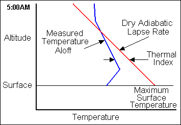 In practice, thermal index is determined from a graph called a "Pseudo-Adiabatic Chart". The
actual temperatures aloft are plotted in degrees C, based on information supplied by the
Weather Service or local measurements taken by airplane early in the morning. These
temperatures are not likely to match any uniform rate of change and, as illustrated here,
may actually increase at lower altitudes due to an inversion. Next the forecast maximum surface
temperature is plotted and a straight line is drawn upward from that point, sloping to the
left at the dry adiabatic lapse rate of three degrees C per thousand feet. This line shows the
expected temperature at any altitude of a thermal rising from the surface with an initial
temperature equal to the maximum forecast for the surface. The distance between the two
temperature lines, measured in degrees C, is the thermal index at the corresponding altitude.
As thermals carry heat to higher altitudes the actual lapse rate will no longer agree with that which existed when the chart was made.
"If thermals are to develop, the lapse rate must become equal to or greater than the dry
adiabatic rate of cooling - that is, the line representing the lapse rate must slope parallel
to or slope more than the dry adiabats."
(2)
In practice, thermal index is determined from a graph called a "Pseudo-Adiabatic Chart". The
actual temperatures aloft are plotted in degrees C, based on information supplied by the
Weather Service or local measurements taken by airplane early in the morning. These
temperatures are not likely to match any uniform rate of change and, as illustrated here,
may actually increase at lower altitudes due to an inversion. Next the forecast maximum surface
temperature is plotted and a straight line is drawn upward from that point, sloping to the
left at the dry adiabatic lapse rate of three degrees C per thousand feet. This line shows the
expected temperature at any altitude of a thermal rising from the surface with an initial
temperature equal to the maximum forecast for the surface. The distance between the two
temperature lines, measured in degrees C, is the thermal index at the corresponding altitude.
As thermals carry heat to higher altitudes the actual lapse rate will no longer agree with that which existed when the chart was made.
"If thermals are to develop, the lapse rate must become equal to or greater than the dry
adiabatic rate of cooling - that is, the line representing the lapse rate must slope parallel
to or slope more than the dry adiabats."
(2)
SKEW-T/LOG-P CHARTS
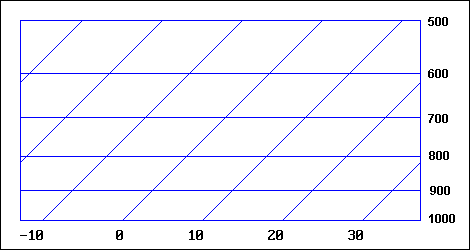 The Pseudo-Adiabatic Chart is the one you are most likely to see on the knowledge test, but one
that you can find on the Internet and that provides a little more information is the Skew-T/Log-P
chart partially illustrated here. The horizontal blue lines indicate pressure levels in millibars, which
also represent altitude (1,000 mb ~ Sea Level, 700 mb ~ 10,000 MSL, 500 mb ~ 18,000 MSL.) The
blue lines at a 45o angle are temperature lines in degrees Celsius. The reddish-brown lines,
approximately perpendicular to the temperature lines represent the dry adiabatic lapse rate. So far
this is about the same as the pseudo-adiabatic chart except that the temperature lines are at
an angle instead of straight up. Now the new stuff. Saturated air doesn't cool at the same rate
as dry air, so we show the saturated adiabatic rate in green. That's the rate of cooling of a
thermal above cloud base, in case you want to know. The yellow lines represent the mixing ratio,
which shows grams of water vapor per kilogram of dry air. They will be labeled on the actual chart
but we are concerned only with their slope here.
The Pseudo-Adiabatic Chart is the one you are most likely to see on the knowledge test, but one
that you can find on the Internet and that provides a little more information is the Skew-T/Log-P
chart partially illustrated here. The horizontal blue lines indicate pressure levels in millibars, which
also represent altitude (1,000 mb ~ Sea Level, 700 mb ~ 10,000 MSL, 500 mb ~ 18,000 MSL.) The
blue lines at a 45o angle are temperature lines in degrees Celsius. The reddish-brown lines,
approximately perpendicular to the temperature lines represent the dry adiabatic lapse rate. So far
this is about the same as the pseudo-adiabatic chart except that the temperature lines are at
an angle instead of straight up. Now the new stuff. Saturated air doesn't cool at the same rate
as dry air, so we show the saturated adiabatic rate in green. That's the rate of cooling of a
thermal above cloud base, in case you want to know. The yellow lines represent the mixing ratio,
which shows grams of water vapor per kilogram of dry air. They will be labeled on the actual chart
but we are concerned only with their slope here.
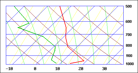 Now that you understand the chart, let's look at how it can be used by a glider pilot.
Temperature and dew point, up to the 100 mb level, are measured twice daily at a number of
locations in the U.S. We stopped at the 500 mb level since that is the beginning of Class A airspace.
In our example, the temperature is plotted in red and the dew point in
green. If we draw a line from the maximum forecast surface temperature, parallel to the dry
adiabatic lapse rate, up until it intersects the actual temperature plot, we can determine the
maximum height of dry thermals. The thermal index at any level is still the difference between
the thermal temperature and the surrounding air temperature, but remember that the temperature
lines run at an angle. The added benefit of this chart is that you can also determine cloud
base. If we draw another line from the surface dew point up, parallel to the mixing ratio lines,
until it intersects the dry adiabatic line previously drawn, we see that in this example, clouds
start to form before the thermal has reached its maximum if it were dry. From that point on up,
we could draw a line parallel to the saturated adiabat and see the new top of the thermal, just
in case you were planning to fly inside the cloud. Although current knowledge tests use the
Pseudo-Adiabatic chart, the Skew-T/Log-P chart appears in recent FAA publications, so it would
be a good idea to become familiar with it.
Now that you understand the chart, let's look at how it can be used by a glider pilot.
Temperature and dew point, up to the 100 mb level, are measured twice daily at a number of
locations in the U.S. We stopped at the 500 mb level since that is the beginning of Class A airspace.
In our example, the temperature is plotted in red and the dew point in
green. If we draw a line from the maximum forecast surface temperature, parallel to the dry
adiabatic lapse rate, up until it intersects the actual temperature plot, we can determine the
maximum height of dry thermals. The thermal index at any level is still the difference between
the thermal temperature and the surrounding air temperature, but remember that the temperature
lines run at an angle. The added benefit of this chart is that you can also determine cloud
base. If we draw another line from the surface dew point up, parallel to the mixing ratio lines,
until it intersects the dry adiabatic line previously drawn, we see that in this example, clouds
start to form before the thermal has reached its maximum if it were dry. From that point on up,
we could draw a line parallel to the saturated adiabat and see the new top of the thermal, just
in case you were planning to fly inside the cloud. Although current knowledge tests use the
Pseudo-Adiabatic chart, the Skew-T/Log-P chart appears in recent FAA publications, so it would
be a good idea to become familiar with it.
WINDS AND TEMPERATURES ALOFT (FD)
Winds and temperatures aloft are forecast twice daily based on 00Z and 12Z data.
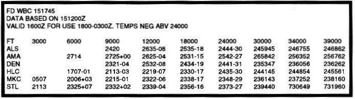
"A 4-digit group shows wind direction, in reference to true north ... The first two digits give direction in tens of degrees and the second two digits are the wind speed in knots... If the wind direction number is between 51 and 86, the wind speed will be over 100 knots... When the forecast speed is less than 5 knots, the coded group is "9900" and read, "LIGHT AND VARIABLE."
No winds are forecast within 1,500 feet of station elevation. Also, no temperatures are forecast for the 3,000 foot level or for any level within 2,500 feet of station elevation."
(3)
WEATHER CHARTS
There are a number of weather charts useful to pilots in assessing weather conditions relative to flying. There was a time when a pilot could walk into a Flight Service Station and look at the charts, but now the best source of charts is via DUATS (Direct User Access System) and a personal computer. We will review the weather charts that are subjects for questions on FAA knowledge tests and use examples from the charts that are supplied when taking the tests.
SURFACE ANALYSIS CHARTS
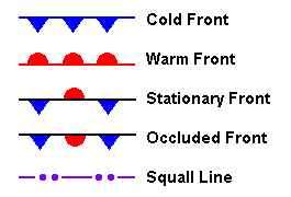 |
The Surface Analysis Chart and the Weather Depiction Chart both show weather conditions at the time the chart was issued. They are issued every three hours. The Surface Analysis Chart is not included in the set of charts that accompany the test, but a few questions about it do appear in the question bank. It shows isobars as solid lines spaced at 4-millibar (mb) levels. It also shows fronts, using the symbols shown here, along with a three-digit number classifying the front as to type, intensity, and character.
|
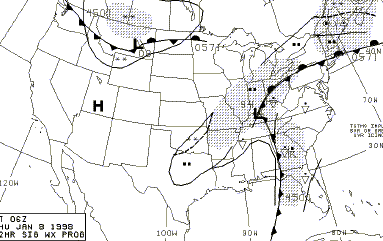
WEATHER DEPICTION CHARTS
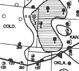 |
The Weather Depiction Chart, shown here, also shows fronts. "The weather depiction chart is an ideal place to begin preparing for a weather briefing and flight planning. From this chart, one can get a "birds eye" view of areas of favorable and adverse weather conditions for chart time."(3)
It shows shaded areas of IFR conditions and outlined areas of marginal VFR conditions.
"IFR = Ceiling less than 1,000 feet and/or visibility less than 3 miles; MVFR (Marginal VFR) = Ceiling 1,000 to 3,000 feet inclusive and/or visibility 3 to 5 miles inclusive; VFR = No ceiling or ceiling greater than 3,000 feet and visibility greater than 5 miles."
(3)
|
WEATHER CHART SYMBOLS
 |
The station model used on the weather depiction chart shows why an area is IFR or marginal VFR. Numbers below the station symbol represent cloud height in hundreds of feet. It is the lowest layer if the sky cover is scattered; the ceiling if it is broken or greater. If the sky is obscured and a cloud height is also shown it represents the ceiling of a cloud layer above or vertical visibility into the obscuration. The number to the left of the weather symbol is visibility in statute miles, shown only when it is 6 miles or less.
|
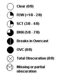 The sky cover symbols shown here are pretty much standard for all weather charts.
| 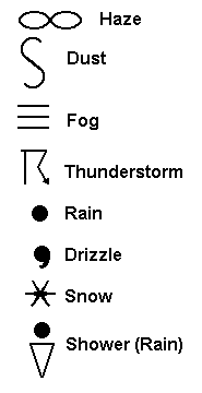 AC 00-45D, Aviation Weather Services, lists 100 symbols for weather that are used on weather charts. Most of them are variations and/or combinations of those shown here.
A single symbol usually indicates intermittent while two indicate continuous precipitation. The triangle for "shower" can be used with rain or snow.
An additional symbol, unique to the weather depiction chart, is shown in the preceding station model illustration. It signifies clouds topping ridges.
AC 00-45D, Aviation Weather Services, lists 100 symbols for weather that are used on weather charts. Most of them are variations and/or combinations of those shown here.
A single symbol usually indicates intermittent while two indicate continuous precipitation. The triangle for "shower" can be used with rain or snow.
An additional symbol, unique to the weather depiction chart, is shown in the preceding station model illustration. It signifies clouds topping ridges.
|
SIGNIFICANT WEATHER PROGNOSTIC CHARTS
Significant Weather Prognostic Charts use symbology similar to the previous charts. They are issued four times daily and show conditions as forecast to be at the time shown on the chart, 12 and 24 hours in the future. Glider pilots are interested in the U.S. low-level prog charts designed for flight planning to 24,000 feet MSL. The format of the chart is two upper panels for 12 and 24-hour forecasts of significant weather and two lower panels for surface condition forecasts for the same periods.
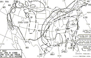 The upper panels depict IFR, MVFR, turbulence, and freezing levels. IFR weather is enclosed in smooth lines and MVFR weather is enclosed in scalloped lines. Turbulence areas are enclosed in heavy dashed lines and indicated by an inverted V symbol. The top and base of the turbulence is indicated by numbers separated by a slash (top/base) that show height in hundreds of feet MSL. No base number indicates that the turbulence starts at the surface, and no top number means that it goes to at least 24,000 feet MSL. A zigzag line shows where the surface temperature reaches freezing. Higher freezing levels at 4,000-foot intervals are shown by a light dashed line with the level in hundreds of feet MSL at the end of the line.
|
 The surface progs show fronts, highs, and lows. Solid lines enclose precipitation areas. Symbols specify the forms and types of precipitation. Precipitation conditions are described further by the use of shading. Continuous precipitation is a dominant and widespread event and, therefore, shaded. Intermittent precipitation is a periodic and patchy event and unshaded. Shading is also used to characterize the coverage of unstable precipitation events. Areas with more than half coverage are shaded, and half or less coverage are unshaded. A bold dashed line is used to separate precipitation with contrasting characteristics within an outlined area.
|
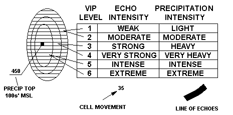
RADAR SUMMARY CHARTS
|
The Radar Summary Chart displays areas of precipitation echoes as illustrated here. The intensity level is shown by contour lines. The outermost area is level 1 to 2, the next is 3 to 4, and the third is level 5 to 6.
Cell movement is shown by an arrow indicating direction and the speed is shown in knots.
The top height displayed is the highest in the area. No figure below the line indicates that the echo base is at or near the surface.
Severe weather watch areas are outlined by heavy dashed lines, usually in the form of a rectangle.
| 
|
COMPOSITE MOISTURE STABILITY CHARTS
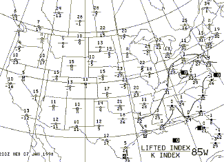 The Composite Moisture Stability Chart indicates stability of the air by the upper number and contour lines at plus 4, zero, minus 4, and minus 8 values of the lifted index.
"A positive index means that a parcel of air, if lifted, would be colder than the surrounding air at the 500-millibar level (about 18,000 feet MSL.) The air is, therefore, stable and would resist vertical motion. Large positive values (+8) would indicate very stable air.
A negative index means that low-level air, if lifted to the 500 millibar level, would be warmer than the surrounding air. The air is unstable and suggests the possibility of convection. Large negative values (-4 or less) would indicate very unstable air."
(3)
The lower number is the K index and is primarily for meteorologists.
The Composite Moisture Stability Chart indicates stability of the air by the upper number and contour lines at plus 4, zero, minus 4, and minus 8 values of the lifted index.
"A positive index means that a parcel of air, if lifted, would be colder than the surrounding air at the 500-millibar level (about 18,000 feet MSL.) The air is, therefore, stable and would resist vertical motion. Large positive values (+8) would indicate very stable air.
A negative index means that low-level air, if lifted to the 500 millibar level, would be warmer than the surrounding air. The air is unstable and suggests the possibility of convection. Large negative values (-4 or less) would indicate very unstable air."
(3)
The lower number is the K index and is primarily for meteorologists.
|
CONSTANT PRESSURE ANALYSIS CHARTS
|
Constant Pressure Analysis Charts are plotted for six pressure levels, which correspond to pressure altitudes as shown here:
For each reporting station the chart plots observed temperature, temperature-dew point spread, wind, height of the pressure surface, and the height changes over the previous 12-hour period.
|
| 850 millibars | 5,000 feet
| | 700 millibars | 10,000 feet
| | 500 millibars | 18,000 feet
| | 300 millibars | 30,000 feet
| | 250 millibars | 34,000 feet
| | 200 millibars | 39,000 feet
|
|
CONVECTIVE OUTLOOK CHARTS
The Convective Outlook Chart is actually two charts showing forecast areas of
thunderstorms for Day 1 and Day 2. Areas are labeled SLGT (Slight),
MDT (Moderate), or HIGH (High), indicating the risk of severe thunderstorms,
based on their number or concentration.
It would be helpful for pilots if the formats for time, wind, and visibility were standardized.
Since they are not, here are some rules that may help: -
Six-digit date/time almost always represent Day/Hour/Minute (DDHHMM). The exception is the valid period
for a Terminal Forecast (TAF), where the format is DDHHHH. The first two "HH" represent the beginning of the period and the last two the end.
This HHHH, beginning/end format is also used without the day in TAF intervals "TEMPO", "PROB", and "BECMG".
All other four-digit times represent hours and minutes (HHMM). The key to identifying a four-digit
time is, if it represents a period of time it will be HHHH. Otherwise it is HHMM.
-
Wind is always given in knots. Its direction (from) is always referenced to true north except in ATIS reports, where it is
magnetic direction. Winds Aloft Forecasts (FD) use a four-digit format for wind direction and speed. The first two digits are true direction in degrees/10. The
last two digits are wind speed in knots. If the speed is greater than 99 knots, 50 is added to the direction and
100 is subtracted from the speed. Thus a 110 knot wind from 270o would be
coded 7710. If you see a direction greater than 36, subtract 50 to get the correct direction and add 100 to get the correct speed.
All other reports and forecasts use a five or six digit format, in which the first three digits represent true direction,
and the last two or three digits represent speed in knots. Sometimes this will be followed by the letter "G"
and two or three more digits, signifying gusts and their peak velocity. Variable direction winds can be indicated by "VAR" for the direction.
METAR reports may show two three-digit directions, separated by the letter "V" (090V180) to indicate
variable direction greater than 60o.
Area Forecasts omit winds less than 20 knots. TAF and METAR consider winds less than three knots as "calm", and code
them "00000KT". Winds Aloft Forecasts consider winds less than five knots "light and variable", and code them "9900."
Wind shear is shown in TAF format as WS###/#####KT, where the first three numbers
are altitude in hundreds of feet, and the five digits after the slash are wind in the format described above.
- Visibility is always given in statute miles. It can be in whole numbers or fractions. TAF and METAR follow the number with "SM"
for statute miles. TAF sometimes uses "Plus 6SM" for greater than 6SM visibility.
Area Forecasts omit visibilities greater than 6SM, and ATIS omits visibilities greater than 5SM.
METAR gives vertical visibility as "VV###", where the three numbers are feet in hundreds.
Practical test applicants should be able to explain reports and forecasts obtained from the above sources with minimal reference to keys. No reasonable examiner would expect an applicant to memorize all the contractions and acronyms used in aviation weather, but the applicant should be familiar enough with the report and forecast formats to determine their significance promptly.
© 2005 Jim D. Burch 602-942-2734
jdburch@att.net
To return to table of contents select TOC
|